Page History: XAML 3D Viewport Element
Compare Page Revisions
Page Revision: 2015/10/13 01:11

|
3D XAML Viewport
|
| Info |
| Category: |
Visual Stimuli |
|
AddIn: |
Base Elements |
| Creator: |
OkazoLab Team |
|
Scope: |
Parent Event |
| Owns Snippets: |
no |
|
Usage: |
Stimulus Screen |
Element actions aligned with different epochs of the parent event
| Epoche | Actions |
|---|
| After Onset | Selected 3D model is shown on the stimulus screen inside the predefined viewport area |
| Control Loop | If Object Tracking is enabled, the tracked object is selected by 2D positional input over the 3D viewport. |
| Before Offset | The viewport is removed from the stimulus screen |
Properties
Generic Properties
| Name | Description | Constraints | Value Type | Upon Change |
|---|
| Camera Orbit |
| Orbit Rotation | Defines an orbital rotation of the camera on the current 3D scene. The vector fields X,Y and Z represent Yew, Pitch and Roll values in degrees. | | Vector3D struct | |
| Orbit Center | Defines the center point of the camera orbit in the world coordinates. | | Point3D struct | |
| Orbit Scale | Defines a scale of the camera orbit relative to the orbit center. The value is in percentages, such that 100% matches to the camera position defined in the current 3D scene. | | Double | |
| Camera Settings |
| Camera Position | Defines a camera location in the world coordinates. The property does not specify the camera direction vector. The direction is defined by the Camera Lookup Direction property. | | Point3D struct | |
| Lookup Direction | Defines the camera lookup vector- a direction in which the camera is looking in world coordinates. | | Vector3D struct | |
| Camera Up Direction | Defines a unit vector that represents the upward direction of the camera (and 3D model projection) | | Vector3D struct | |
| Near Plane Distance | Defines a distance from the camera to the camera's near clip plane | | Double | |
| Far Plane Distance | Defines a distance from the camera to the camera's far clip plane | | Double | |
| Field of View | Defines horizontal bounds of the camera's projection, as degrees between the camera's position and the image plane | | Double | |
| Object Tracking |
| Is Tracking | Enables tracking and selection of 3D objects with a 2D positional device, e.g. mouse or eye-tracker. The tracking returns a name of the closest object pointed on the current projection of 3D model | | Boolean | |
| Tracked Object | Returns a name of the pointed 3D object among all objects on a 3D scene. The object name has to be defined in the XAML 3D model. When no object is pointer the property returns an empty string. | | String | |
| Tracked Point | Returns 3D coordinates of the focal dot on the pointed 3D object. When no object is pointed, the property returns the zero point. | | Point3D struct | |
| Tracking Distance | Returns a distance from the camera to the focal dot of the tracked 3D object (in the world units). When no object is pointed, the property returns the zero. | | Double | |
+=== Properties inherited from clVisualElement ===
| Name | Description | Constraints | Value Type | Upon Runtime Change |
|---|
| VISUAL APPEARANCE |
| Alpha Masking | Defines whether the visual content rendered by this element will be used as an opacity mask which is applied onto the given event surface. The active opacity mask allows one to expose pixels of the parent event surface through a solid background of the given event. If the value is true, the darker pixels of the content will make more transparent holes on the entire event surface. | | Boolean | |
| AntiAliasing | If true, the rendered content will be anti-aliased for smoother visual appearance. If false, rendering will be authentic to its source, e.g. a bitmap. | | Boolean | |
| Position | Defines the position of the element viewport on the screen. The position can be set in any of three coordinate systems: a) pixels, b) polar, c) central. | | clPoint | |
| Size | Defines the size of the element viewport on the screen. The size can be set in any of three coordinate systems: a) pixels, b) visual degrees, c) 'relative-to-screen' size. | | clSize | |
| Z Order | Indicates the current depth order of the element viewport on the surface of the parent event. The greatest number corresponds to the top position. The order can be changed by moving the element up and down in the element list. | | Int32 | |
| Pivot Point | Defines the pivot point (coordinate and the rotation centers) within the element viewport. | | stAlignment or Int32 | |
| Visible | Defines whether the element is currently visible on the event surface. The property is convenient for switching visual content on and off. | | Boolean | |
| Rotation | Defines the rotation angle (in degrees) of element viewport relative to the its pivot point. | | Double in the range 0..360 | |
| EFFECTS |
| Transparent Color | The color of the original pixels of rendered content that will be set as transparent. | | stColor | |
| Transparency Tolerance | Tolerance ratio for choosing colors that become transparent. Zero means that effect is not applied, 1 denotes that all colors will become trasparent. | | Int32, range (0..100) | |
| Color Mask | Produces a multiplicative combination of the original pixels and the selected mask color (except the alpha channel). The effect emulates a look through a colored glass. White or transparent mask color doesn't change the original pixels. | | stColor | |
| Opacity | Opacity of the rendered content. | | Int32, range (0..100) | |
| Contrast | Contrast of the rendered content. | | Int32, range (-100..100) | |
| Brightness | Defines the brighness of the rendered content. | | Int32, range (-100..100) | |
| Saturation | Saturation of the rendered content. | | Double | |
| Pixelation | Defines the pixel scale of the rendering. | | Int32, range (0..100) | |
| Blurring | The radius used in the gaussian blur of rendered content, as a pixel-based factor. The default is 0 which means no blurring. | | Int32 | |
| POSITIONAL JITTER |
| Reset Jitter | Set to true at runtime to reset the current positional jitter. | | Boolean, set true for action | |
| Current Jitter | Jitter range, in pixels (non inclusive). | . | clSize | |
| Jitter Range | Jitter range, centered at the original position of the element. | . | clSize | |
+=== Properties inherited from clLibraryElement ===
| Name | Description | Constraints | Value Type | Upon Runtime Change |
|---|
| Material List |
| Selected Index | Defines the index of the active item in the material list of the element. | | Int32 | A change causes the current item to be reloaded and an update of the element. |
| Selected Item | Defines the name of the active item in the material list of the element. The name matches to a name of item in the Material Library | | String | A change causes the current item to be reloaded and an update of the element. |
| Item Count | Returns the total number of items in the material list of the element. | | Int32 |
| Equalize RGB | The property is only available in the visual element. If the value is true, the average RGB pixel intensity will be equalized across all items in the material list. You can turn on this property, when you need to obtain a luminance-balanced set of visual stimulus. | | Boolean | |
+=== Properties inherited from clElement ===
Inherited properties of clElement
| Name | Description | Constraints | Value Type | Upon Change |
|---|
| Control |
| Is Enabled | If set to false the element is completely omitted when the experiment is run. | | Boolean |
|
| Title | Title of the element. | | String |
|
XAML 3D Viewport element renders a dynamic viewport projection of 3D models stored in the XAML 3D format.
Description
XAML 3D is a sub-branch of the
XAML markup language intended for description of 3D models of any level of complexity. In contrast to other 3D formats, XAML 3D allows dynamic adjustments of all 3D model's parameters (e.g. object positions, materials, lighting) via scripting or
XAML data binding. (Note that if you want to use static 3D models with a camera control, you may prefer the
3D Viewport element in EventIDE, because the latter supports more common 3D formats, e.g. the Wavefront obj). The XAML 3D viewport element is the best choice for creating 3D animations, interactive 3D scenes and the hittest-based object tracking. Multiple 3D models can be loaded into element's material list to form a switchable 3D stimulus set.
Loading 3D models
Before you deploy the XAML 3D Viewport element, you need to load XAML 3D models into
Material Library.
+
Picking up the XAML 3D presets
EventIDE offers a XAML preset gallery, which includes a number of basic 3D models. Once you select a 3D model in the gallery, it will be added into Material Library. Before adding a model, you can change its material color. You can find the basic 3D models in the last row of the gallery (Library ribbon tab->Add XAML vector shapes):
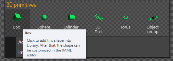 |
| Primitive 3D models in the preset gallery |
Importing the XAML 3D files
XAML 3D models are stored in a special file format supported in several 3D editors:
You can import existing XAML 3D files into Material Library using the 'Load Materials' command (or, simply dropping the XAML files into the Library panel). If a 3D model has references to external material files, the materials will also be automatically imported.
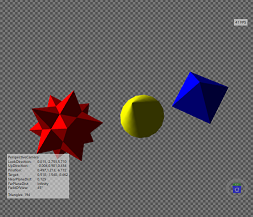 | 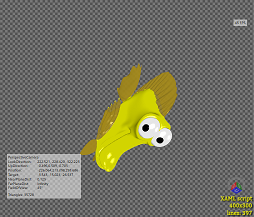 | 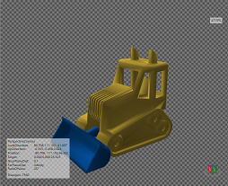 |
| Examples of the XAML 3D models rendered in a viewport. Model's statistics is shown in the superimposed text blocks. |
Editing 3D models
A XAML 3D model is defined by a markup script, which can be previewed and edited in EventIDE. The script is made of a hierarchy of description tags for: camera, lighting, materials, transforms and meshes. You can see it on the next screenshot.
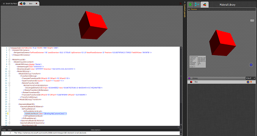 |
Editor for XAML 3D script (click to enlarge).
Note the highlighted line that show the data binding syntax.
The data binding makes the material color linked to a user variable that can be changed at runtime. |
Deploying the 3D XAML Viewport element
Creating a single 3D stimulus
- Select an event, which will contain a 3D stimulus
- Add a new 3D XAML Vieweport element and select it in the Elements panel
- Open Material Library and start dragging a selected 3D model
- Drop the model over the 3D XAML Vieweport icon in the Elements panel
- If required, adjust the position and size of the 3D XAML Vieweport on the event surface
- If required, modify other element's properties (e.g. the camera orbit position) in the Properties panel
Creating a switchable 3D stimulus set
- Repeat the above steps, except that this time you drag multiple 3D models into the 3D XAML Vieweport element.
- If required, switch the models by the 'Selected Index' or 'Selected Item' properties of the 3D XAML Vieweport element.
Controlling camera settings
Beside XAML data binding, the 3D XAML Viewport element enables direct control of camera settings via the element's properties. These properties include the camera position, look-up direction, up direction, near and far plane distance and field of view. Once a new 3D model is selected in the element's material list, these properties receive the initial values defined in the XAML 3D script. If you change the values, the viewport projection is automatically updated.
Animating the camera orbit position
3D animation is often generated by moving a camera over a 3D model. However, beside setting a new camera position on each animation step, you have to also recalculate the camera directions settings relative to the 3D model. The 3D XAML Viewport element offers much easier way to generate 3D animation with the camera orbit rotation. In this type of motion, the camera 'focus' point is fixed at the selected point (usually the coordinate origin) on a 3D model. The camera distance to the focus point is also fixed. To produce animation, you just change the Yaw, Pitch and Roll angles defining the orbital position of camera. The camera orbit angles are represented by the 'Orbit Rotation' property of the 3D XAML Viewport element. The property has a Vector3D data type, in which X,Y and Z fields represent the Yaw, Pitch and Roll angles respectively. For instance, to produce the 'Earth' rotation over a model you can use just one code line:
OrbitRotation.X=OrbitRotation.X+2.5;
When necessary, the camera 'focus' point and distance can be adjusted with 'Orbit Center' and 'Orbit Scale' properties of the 3D XAML Viewport element.
Dynamic object tracking
The 3D XAML Viewport element allows dynamic object tracking with 2D positional input over a projection viewport. Imagine a participant moving a mouse over a viewport. The 3D XAML Viewport element reads the mouse posotion and build a 3D ray orthogonal to the projection (or, camera) plain. If the ray touches any 3D object in the model, the element returns a name of this tracked object, 3D coordinates of touched point on the object surface and the camera-object distance. If the ray penetrates through several objects in the model, the closest object to the camera plane is selected. See the following example of object tracking on a animated 3D scene recorded in EventIDE:
Other positional devices, such as eye-trackers, joysticks, etc can also used for the 3D object tracking.
Notes
- To enable the full hardware acceleration for 3D XAML Viewport element rendering, you can turn on the hardware composition mode in properties of the Experiment object.
- 3D Viewport element has faster rendering than 3D XAML Viewport element.